

I recently did a live streamed church service from home, and along the way learned what is needed to get certain types of microphone to work.
I have a couple of microphones I use for video work – I have a Rode VideoMic GO shotgun microphone and a Rode SmartLav+ label microphone.
I use my Canon DSLR for filming stuff, and almost any external mic is a huge improvement on the built-in one, so this has worked well.
However, when I plugged either of these into my laptop for the broadcast, I had to boost the gain, which in turn introduced a hum/buzz, and it was also picking up some internal computery noises. No problem, think I – I have an old mixer with mic pre-amps, let’s use that, and provide a line level input to the laptop.
No joy at all – no signal. These mics both have 3.5mm TRS jacks (actually the SmartLav comes with a TRRS, but I have a converter). My Mixer has XLR or 1/4″ TS or TRS inputs, so I try various converters. Absolutely nothing.
I then discover that these sort of microphones (unlike, say, an SM58) need a power supply, in the form of a voltage between the tip and the sleeve – called a DC Bias. This is only around 3v, and if you try to run phantom power down it, you will most likely fry the mic.
I found a few old YouTube videos of inline power supplies people has bought on eBay – but my searches brought up nothing. Until I found this page: Powering Microphones by Tomi Engdahl. I had a look at his circuits, and thought to myself, “I could make one of those”, so I did, and it worked!
It does give a bit of a “thump” when you plug it in, or turn it on, which I guess is due to the capacitor (presumably I have the wrong sort), but it provides a solid, if slightly low, level from the smartlav to the mixer pre-amp. I wonder if 3 AAs might have been a better bet, and 3V is a little low. Or maybe the 2.2K resistor is to high (or low), and provides too much (or too little impedance)? I confess I lose my way a little with microphone impudence, but figured it was worth a shot, as I was unlikely to blow up either my microphone or the mixer from 2 AA batteries.
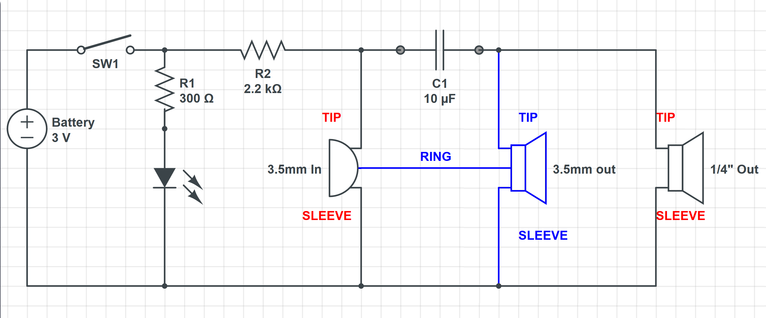
My final circuit is shown below. I ordered all the parts from CPC Farnell, as follows:
- Black ABS Potting Box – 100x50x25mm
- Black Potting Box Lid – 100x50x25mm
- 3.5mm Jack Socket, 3 Pole
- 6.35mm (1/4″) Jack Socket, 2-Pole
- 2x AA Battery Holder
- Rocker Switch, DPST,
- LED, Blue, 3mm, 3.5V
- 300 Ohm Resistor, 0.6W
- 2.2 kOhm Resistor, 0.5W
- Capacitor, 10 µF
I originally designed it with a single 3.5mm jack, however the order quantity was 2, so I decided to have a stereo 3.5mm output option, with the rings of the 2 jacks directly connected (shown in blue).
The only purpose of the LED is to show when the box is switched on.
A days work drilling out the mount holes for the LED, jacks, and switch, and the job was a good ‘un. It was all a little bit tight in the potting box, and I don’t think a 3 AA battery holder would fit inside, but I’m quite happy with it, and it even works!